Page 10 of 11
Re: L.E.D. Navigation/Strobes/Interior Lights
Posted: Tue Jan 27, 2015 4:34 am
by LBPilot82
Here is what I've got...
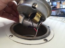
- GetAttachment.aspx.jpg (8.28 KiB) Viewed 17798 times
The red wire coming up is the 12V power. It splits between the light and the motor capacitor. The white/black is ground which goes to the motor body. Looks pretty parallel to me. My thinking is the LED has less resistance and doesn't allow for enough current to get the motor running. The easy path of low resistance through the LED vs. the incandescent allows the current to basically run "around" the motor. Perhaps the motor capacitor has something to do with that???
Re: L.E.D. Navigation/Strobes/Interior Lights
Posted: Tue Jan 27, 2015 3:22 pm
by GAHorn
The capacitor is a noise filter.
Re: L.E.D. Navigation/Strobes/Interior Lights
Posted: Tue Jan 27, 2015 5:41 pm
by DaveF
The LED is higher resistance than the bulb. With the same 12V applied it draws less current.
Re: L.E.D. Navigation/Strobes/Interior Lights
Posted: Tue Jan 27, 2015 8:45 pm
by GAHorn
WAIT A MINUTE!.... Are you certain your beacon doesn't require a TWO-contact lamp such as an 1157 base ?
Re: L.E.D. Navigation/Strobes/Interior Lights
Posted: Wed Jan 28, 2015 12:30 am
by LBPilot82
gahorn wrote:WAIT A MINUTE!.... Are you certain your beacon doesn't require a TWO-contact lamp such as an 1157 base ?
Yes, it has a GE1914 in it which is basically an 1156 that is a little bit taller. So it uses a single contact at the bottom and the keeper tabs are equal distant from the bottom (not staggered like the 1157). I originally bought an 1157 LED but found out it wouldn't fit.

DaveF wrote:The LED is higher resistance than the bulb. With the same 12V applied it draws less current.
I guess that would be correct! Hmm... So I wonder what is going on then. Maybe I need to get back there with a meter and see what is happening with the voltage to the motor with each bulb installed. This one has me stumped...
Re: L.E.D. Navigation/Strobes/Interior Lights
Posted: Wed Jan 28, 2015 2:20 am
by DaveF
Not that it really matters, but I can't find a reference to a GE 1914 bulb anywhere. But a
GE 1940 is a standard rotating beacon bulb.
Is this a tricky deal where the center contact on the bulb is supposed to push a spring-loaded contact to make a ground for the motor, or something, but if the bulb contact is the wrong shape it doesn't work? I know that doesn't agree with your report that the motor runs with no bulb ...
Re: L.E.D. Navigation/Strobes/Interior Lights
Posted: Wed Jan 28, 2015 4:58 am
by GAHorn
I don't think an L.E.D. has a higher resistance. I believe it has a lower resistance.
It is a light-emitting Diode. A Diode passes current.
I believe it might be passing so much current that it appears as a short to the motor (and therefore no current is available to it), and the solution might be to install a resistor in series ....to the LED...in order for the motor to have available sufficient current to perform work.
Let's try an experiment. Wire a resistor in series with the LED and see if both the LED and the motor work. The problem might be figuring out how much resistance is appropriate, but for starters you could even use the incandescent lamp in series (just to check out the theory.)
Looking at other resources, I think a 1 watt, 300 ohm resistor might be the trick. Ceramic resistors in this range are available at Radio Shack for just a dollar, if the experiement works. (Remember to allow the resistor to shed heat.)
Re: L.E.D. Navigation/Strobes/Interior Lights
Posted: Wed Jan 28, 2015 6:22 am
by LBPilot82
Maybe I've got my GE number wrong... I'll check.
George, looking at other resources... specifically automotive, it is normally required to wire a resistor in parallel with an LED used as a turn signal. Now I'm not sure this applies here but with an automotive turn signal that is changed to LED, the turn signal flashes much faster than with incandescent. Wiring a resistor in parallel will correct the turn signal rate back to normal. I wonder if this means I should wire a resistor in parallel in order to fool the system into thinking nothing has changed. Wiring a resistor in parallel to a load (LED in this case) will decrease the total resistance to the circuit indicating that (in the automotive example) the new LED has more resistance than the incandescent. If you look at any auto supply store in the LED section, they sell standard resistors to be wired into turn signal LED circuits.
One thing I have already tried is changing from the LED you recommended:
http://www.ledlight.com/s25-36-super-br ... light.aspx
to a different style LED like this one:
http://www.ledlight.com/s25-27-smd-5730 ... ac-dc.aspx
I'm not exactly sure of the difference but using an LED as shown in the second link, I got about a half rotation out of the motor when I first turned it on and then it quit. I wonder if the motor of the beacon is having the same problem that an automotive turn signal flasher has when changing to LED.
I will definitely experiment with this as it has me very interested.
Re: L.E.D. Navigation/Strobes/Interior Lights
Posted: Wed Jan 28, 2015 2:06 pm
by Bruce Fenstermacher
If I understand the circuits being discussed, you can not put a resistor in series with the LED. The LED won't work or work correctly. Another thing to keep in mind is that in the truest sense an LED is just a single light emitting diode. Most things called LEDs today are not just a single diode but at least a diode and a resistor and many cases much much more.
A resistor in parallel as Richard said would not change the voltage to the LED but increase the load of the light circuit.
Re: L.E.D. Navigation/Strobes/Interior Lights
Posted: Wed Jan 28, 2015 2:42 pm
by johneeb
Richard,
Try checking the motor ground, it sounds like the motor maybe trying to find a ground thru the bulb.
Re: L.E.D. Navigation/Strobes/Interior Lights
Posted: Wed Jan 28, 2015 2:56 pm
by GAHorn
Many modified circuits do indeed place a resistor in parallel to the LED... for the purpose of signaling that a valid load is placed. This can be a solution to the problem of your recent-mfr automobile not sensing the LED is installed and the on board diagnostics displaying a fault. (This was what I had to do to make the bed-lights work in my new Ram.)
But it seemed to me that the present problem (in which the motor will run with NO lamp at all ... but will not run with an LED installed in parallel... might be a loss of current to the motor due to a perceived short in the route of the LED.
I came to the idea of a resistor in series due to this article:
http://electronics.stackexchange.com/qu ... ors-in-led
johneeb wrote:Richard,
Try checking the motor ground, it sounds like the motor maybe trying to find a ground thru the bulb.
How would that explain that the motor runs with no lamp installed whatsoever?
Re: L.E.D. Navigation/Strobes/Interior Lights
Posted: Wed Jan 28, 2015 4:48 pm
by johneeb
johneeb wrote:Richard,
Try checking the motor ground, it sounds like the motor maybe trying to find a ground thru the bulb.
How would that explain that the motor runs with no lamp installed whatsoever?[/quote]
George, I considered that but have seen enough faulty wiring to not discount the odd possibilities.
Re: L.E.D. Navigation/Strobes/Interior Lights
Posted: Wed Jan 28, 2015 5:04 pm
by cessna170bdriver
Bruce Fenstermacher wrote:If I understand the circuits being discussed, you can not put a resistor in series with the LED. The LED won't work or work correctly. Another thing to keep in mind is that in the truest sense an LED is just a single light emitting diode. Most things called LEDs today are not just a single diode but at least a diode and a resistor and many cases much much more.
A resistor in parallel as Richard said would not change the voltage to the LED but increase the load of the light circuit.
If the LED is "rated" for 12 volts, it already has an resistor or some other current-limiting circuitry in series with it. If you put
another resistor in series, it will either dim or not work at all. A "raw" LED is just a diode, and you'll burn it up at much over 0.7 to 1.0 volts. You won't find these in a "bulb" package.
Like I said before, if the motor and bulb are truly in parallel, neither one will affect the operation of the other as long as the total current for both is less than the rating of fuse or breaker protecting the circuit.
Re: L.E.D. Navigation/Strobes/Interior Lights
Posted: Wed Jan 28, 2015 5:39 pm
by johneeb
Miles,
Been reading a little (dangerous) on the site George listed and they noted as you did that LED are diodes and must have a resistor already installed in series. It occurred to me to ask what would be the effect of having the polarity to the bulb (diode) reversed?
Re: L.E.D. Navigation/Strobes/Interior Lights
Posted: Wed Jan 28, 2015 5:51 pm
by DaveF
Depends on the design of the LED module. If it's just a string of LEDs or an LED with a series resistor, then reverse bias will mean no light. No idea what Richard's lamp is, but most LED lighting uses dc-to-dc converters, which are often designed to be polarity insensitive. Hook 'em up either way, the circuit takes care of it for you. My LED landing lights are that way.